I have a Gaggia Baby Class. She may not look like much, but she’s got it where it counts. I’ve made a lot of special modifications myself1And, like the Millennium Falcon, she’s broken down more times than I can count, to which I’ve said “It’s not my fault!” more times than I can count. But things have settled down and, except whenever I start tinkering again, she consistently produces coffee happiness with no trouble at all.. This page documents the results of years of tinkering research. The same ideas would work with many other coffee machines, and will work, especially, with other Baby and Classic Gaggia machines2Not counting the unhappy period between about 2015 and 2019 when Gaggia, under ownership of Philips, replaced all the good stuff inside the machine with a newer, cheaper design. I understand this travesty is now a thing of the past but if buying a new Classic be very careful not to get one that originated during those wilderness years..
Before I go on. If any of this inspires you, be very very aware that there’s 240VAC3For North American readers, 120VAC can also be quite nasty and, even, mortiferous. inside your coffee machine and this many VACs can make you very very dead4Yes, I know it’s the current that kills you. But it’s the potential difference that drives the current.. Never take the machine apart without switching it off, removing the mains cable, switching off the mains socket, removing the plug from the socket and double checking you’ve done all of these. Also remember that coffee machines contain water and water conducts electricity5Not mention all the other dangers of dihydrogen monoxide.. Be ever vigilant.
The mods started is a simple Arduino-based6Arduino Nano, specifically PID controller but over the years I have also made some handy hardware changes. All of this is documented below. But first: what can this machine do that it could not do new from the factory? Here’s a list of features.
All told, I can produce a pair of perfect Flat Whites in just under six minutes7Check out the video! from switching the machine on cold. Which makes Mrs Tom happy.
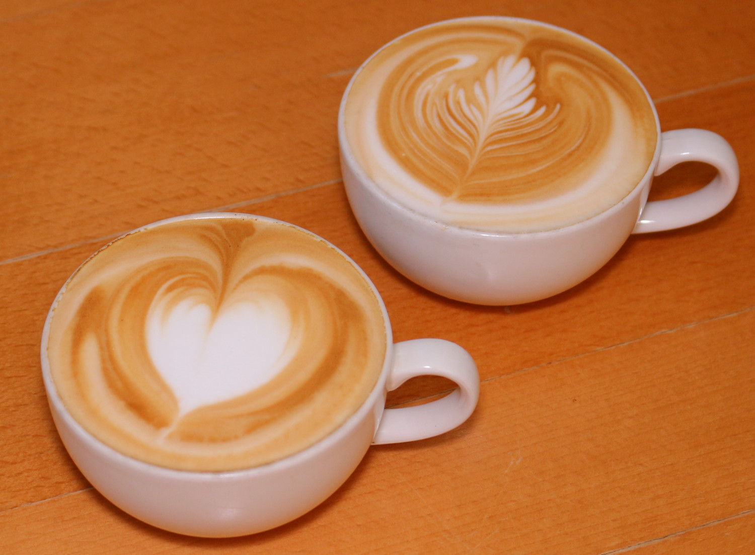
Not a stock photo. I made these!
The modifications
The electronics mods are now the Hot Metal Brewbot open source project on GitHub. My first published version of this, rev 1, is documented is here.
The present version, rev 2, is documented here.
The other non-electronic changes are here.
Blog posts
From time to time, I have new ideas or information I want to share. Below are blog posts I have written when inspiration struck. These have eventually all led to a better machine.
- The perfect temperature control algorithm.
- Improving the brew head temperature hardware mod.
- Physical characteristics of the boiler.
- Wiring diagram for the Gaggia baby Class.
- Doubling the boiler’s heating power: Initial thoughts, implementation and a video.
- Better backflush behaviour.
- Gaggia Baby Twin front panel comms protocol.
- How to mount a flow meter easily.
- Wiring tricks and boiler terminal connectors.
- Water level meter.
- What to do about scale.
- Temperature probe design.
- Where to mount a temperature probe?
- Zinc plating parts to prevent corrosion.
Things I think I might do in the future
- Calibration mode in the firmware for the temperature probe and flow meter. It’s got a USB port, after all, so why not? I could write calibration values into EEPROM rather than hard coding them.
- Add a second temperature sensor (as mentioned above). So I know how full the boiler is. And how stable the temperature is.
- Design a simple, easy to replicate temperature probe.
- Implement a simple, cheap temperature-based flow meter.
- Preinfusion: is this of any real value? Would be good to know.
- Temperature profiling: I am told the latest and best machines profile the temperature over the volume of the shot. I vaguely wonder whether my precise temperature control algorithm could give some ability to do temperature profiling. I find, when I measure the brew water, that it comes out at exactly the modeled brew head temperature. When water is flowing through the system, it is possible to cool the brew head fairly rapidly and with double heating power, it is possible to heat it fairly quickly. There must be some envelope within which I can play here.
See also
I am not alone in all this madness. As far as I am aware, the most active community of Gaggia modders in the Gaggiuino project which has a very active Discord server including a marketplace where members are able to buy/sell/swap parts with each other.
Other older projects I have encountered are here and here.
Let me know if there is anywhere else you think I should link to.
| ↑1 | And, like the Millennium Falcon, she’s broken down more times than I can count, to which I’ve said “It’s not my fault!” more times than I can count. But things have settled down and, except whenever I start tinkering again, she consistently produces coffee happiness with no trouble at all. |
|---|---|
| ↑2 | Not counting the unhappy period between about 2015 and 2019 when Gaggia, under ownership of Philips, replaced all the good stuff inside the machine with a newer, cheaper design. I understand this travesty is now a thing of the past but if buying a new Classic be very careful not to get one that originated during those wilderness years. |
| ↑3 | For North American readers, 120VAC can also be quite nasty and, even, mortiferous. |
| ↑4 | Yes, I know it’s the current that kills you. But it’s the potential difference that drives the current. |
| ↑5 | Not mention all the other dangers of dihydrogen monoxide. |
| ↑6 | Arduino Nano, specifically |
| ↑7 | Check out the video! |
Hi Tom,
Found your blog through http://int03.co.uk/blog/
I’m about to embark on a similar project – is there a chance I could buy a board (ideally two in case I screw up) off of you? That’d save me a lot of time in terms of getting a prototype up and running. Please let me know if there’s a better way for me to get in touch to arrange payment – I’m in Canada but I’d obviously be happy to cover postage and handling as well.
Thanks!
Ryan
I’ll e-mail you.
I have some questions.
1 – Will you update the “doubling the Gaggia boiler power” with some schematics?
2 – Are you using your own PCB with triacs as a substitute to external power supply for arduino and SSRs to save space?
1. I can do that, yes. But not this week. It’s easy to describe, though, place a high-current diode in parallel with each heating element, but with the diodes back to back. I also added a second thermal fuse, so there’s one on each side and I added a 13A quick blow fuse. The quick blow and thermal fuses are in series with the power to the element/diode circuit. This configuration causes twice the voltage to be applied over each element (i.e. four times the power) but for only half of the mains AC cycles (so a net effect of twice the power). The fuses are intended to protect against various diode failure scenarios (especially blowing short circuit which would cause one element to get very hot). I found that the diodes needed heatsinks.
2. The SSRs and opto-isolaters on my PCB are exactly what you find in an external SSR, but they’re a lot cheaper and more customised to my needs. My PCB does also provide power to the Arduino. In addition, it contains an analogue circuit for conditioning the heat sensor signal and another circuit for detecting mains zero-crossover and a piezo-buzzer and all the necessary capacitors on I/O lines to suppress electromagnetic noise and possibly more I can’t recall off the top of my head.
Thanks.
1 – A photo or picture with comments wil;l help alot.
2 – So my idea to use just PID and another one for secvond moiler in my Baby twin is ok. with less features.
For mor hustle and pimpimg I suggest you install the preheat coil and replace the OPV with external one located before preheat coil. not on boiler. This will prevent hot water discharge through OPV – cold only will go back to tank.
Additional SSR or triac control line with U shaped boiler to keep the water actively pre heated will make the machine travel faster than light.
I’ve written a post documenting the double boiler power here.
In principle, my board could control both heaters, but then you’re one TRIAC short. If you don’t want to control the pump, that’s okay. I have not tested the dual temperature probe circuit, but it ought to work.
Hi Tom, love reading about your endeavors with the Baby. I too have one that a rescued from the tip last year. I am currently modding it too, writing code to do most of the ideas you have listed. Will be using a 4D Systems touch screen too!
One thing, are you Tom B from Pinetown by any chance?!!
Hello Andrew, lovely to hear from you. I was just wondering whether you were the Andrew Fraser I knew when I saw your question at the bottom. Yes, I am that Tom B.
Rescuing a Gaggia Baby from the tip is a total bargain – I paid £100 for mine second hand (many years back now). I like the idea of a touch screen. Have briefly googled 4D Systems but it was not immediately obvious to me how you drive the thing. Is it all via wifi?
I am happy to share any wisdom/knowledge with you but I also know that the real fun is in doing it yourself!
What a small world! I thought I recognised you and Julie in the blogs!
The 4D Systems screens are supposed to be quite straight forward. They can do all the hard work on their own, or let an Arduino do it. I’m using a Nano for mine. And the 4D PC software means it’s very easy to design the screens.
I do want to pick your brains about PWM on the vibe pump…
And I certainly want to have a go at doubling the boiler power, seems daft not to!
I’ve used my work email, so feel free to say hi offline.
Andrew
I’ve replied by e-mail. Had some biggish attachments so might get rejected by some e-mail filter.
I’ve been playing around with pre-infusion for a while. It’s worth implementing because it add consistency to your shots by removing any chance of channeling, using up your full puck everytime.
Any chance you still have a board or two available? I’m excited to jump into this project with a recent acquisition of a used classic.
Yes, I have. I’ve sent you an e-mail.
Hello
I recently thought about modifying my steam wand.
My options were:
-Rancilio Silvia V1 Steam wand (too expensive)
-Make Steam wand from scratch (don’t have all the tools, would cost similar to Silvia Steam mod
and I came across your teflon Tubing!!
Could you let me know if i got this correctly?
1. buy ID 6mm of Teflon Tubing
2. Remove steam attachment of Gaggia.
3. Shove teflon tubing on top of existing stainless steel steam wand
4. Attach steam nozzle (What kind did you buy?)
The teflon tubing can be used to improve any metal wand, but it doesn’t make any difference to the nozzle. It’s just to make the wand easier to clean and to keep the steam from losing heat as it travels through the wand, creating a burn hazard.
The Gaggia wand doesn’t lend itself to replacing the nozzle as it doesn’t have a thread on the end. (Mine didn’t, anyway).
I am using a Rancilio Silvia wand (about £13 on ebay UK at present). I have replaced the single hole nozzle with a three hole nozzle. That needs quite a high steam temperature and so alternate temperature control is a must.
Thank you for the reply.
Another question.
I’m pretty happy with my Gaggia Baby Twin, except Steam power.
Should I just follow non-Arduino based mods from 1~6?
on 5th you said “Fifth, if you are very brave and adventurous and careful and probably only after you’ve also done the Arduino mods, double the boiler power. ”
is Arduino mode necessary for double boiler power?
All of those mods have value in themselves. I think you could get away without the Arduino mod for doubling the boiler power. The disk thermostats should handle the current (as discussed here). When I first did this, I was quite nervous about it and used the Arduino controller to hold back the current from the maximum 2.7kW. I have gradually increased that over time and it’s been fine. (Well mostly fine, the TRIAC on the Arduino controller got a dry joint eventually but that wouldn’t happen without the Arduino controller). I now run the boiler at 2.5kW maximum which is pretty close to the 2.7kW.
However, none of those mods are going to help significantly with steam power on the Twin. That is limited by the power of the steam boiler which is, I think, 1kW. And, if the pump is pulsed too slowly, then the thermostat on the steam boiler will engage and limit the power to even less than 1kW.
I don’t know whether the thermostat engages during steaming. I have recently acquired a Twin to play with but haven’t yet tested this – it’s a little fiddly to do, I think. However, I suspect it does. At 1kW, you should be able to evaporate 0.44ml/s (latent heat of vaporisation is 2260J/g and 1g is about 1ml). I’ve just done a quick test and got about 0.37ml/s (I ran steam into a jug full of cold water for a minute and weighed jug before and after. Pretty much all the steam condensed into the water.) So there is, perhaps, a 20% steam flow improvement to be had by adjusting the pump’s duty cycle – but I haven’t thought of a way to do that without replacing the controller board.
My current Arduino board is not suitable for the twin. At the very least, it needs an extra TRIAC output for the steam boiler and the TWI pins (SDA and SCL) need freeing up to talk to the front panel PCB. I am working on a new board which does this and adds some other benefits (including a water level meter).
Since you have a Twin, could you answer a question for me? On mine, the steam water flow is as follows: main boiler -> pipe -> steam boiler -> pipe -> steam valve -> pipe -> wand. Is your the same? I would have expected the steam valve to come before the steam boiler. That would mean the steam boiler wouldn’t experience the strain of 15 bar when brewing and also that the steam wand wouldn’t get filled with water that needs pumping out before steaming can start.
Hello. Do you have a wiring diagram for your installation of PID for the Baby Twin? I can’t seem to find any online. Thanks.
Hi Tom, your work on the PID has been big inspiration to me. After lots of preparation I’m slowly putting my PID together. I have however gaggia classic and use ESP32 so not copying your code, only the ideas 🙂
I’ve wired my machine and taking measurements and I can’t figure out some processes:
My flow meter works since today and based an 4-5 experiments I read the machine takes in ~100g of water used per shot. My (current) shot recipe is 30g out. I’m guessing the other 70g go for building up pressure, filling up the brew head and wetting the puck. What’s your experience?
With my current (custom, but still proportional) PID I see lag of ~7 seconds between switching power off and side temp maxing out. The plain side needs extra 7 seconds. Here is example https://imgur.com/UbY47BY
This puzzles me a lot. I can’t figure out where the energy is stored, given I measure the side temp with thermocouple fitted in the thermostat hole so it’s as close as it gets to the heater.
Great to hear from you Georgi.
I find I need about 100ml of water for a 60ml double shot. The difference is what stays in the puck. You can measure the weight of your portafilter before and after taking the shot to see how much this is. For a single shot I could imagine it might be a higher ratio as I find single shot baskets tend to have more empty space than they need. Nonetheless, 70ml out of 100ml sounds on the high side. I immediately wonder about calibration of your flow meter and how it is plumbed into the machine. Its response is probably a bit non-linear so you might have calibrated and a different flow rate to the one you use for brewing and therefore have a calibration issue. In terms of plumbing: have you mounted it downstream of the over-pressure valve? It should be connected to the water tank on one side and a T piece on the other with pump and OPV connected to the T.
The 7s latency with the thermostat mounting hole is consistent with the experience of Hans. This will be caused by a number of factors. The mounting point itself has its own thermal inertia. And the thermocouple will have at least some thermal resistance to heat flow from the mounting point. I suspect these are the major factors.
Hans has been experimenting with a modification for my model predictive control algorithm that allows for a sensor mounted on the element side. He reports that it works well. It is based on a generalisation of my algorithm which I am trying out for the Marlin 3D printer firmware. (PR here if you are interested). An alternative is just to use my algorithm as it is pretending that you mounted your sensor on the plain side as I did. The latency is similar and it should work. But it might result in the water, brewhead, etc. temperatures being off by a fixed amount – if you care about that level of detail.
The flow meter is connected as you describe. Should be measuring net input. I calibrated it today pumping 100 grams of water and calculated 1 pulse to equal 0.22 grams. For 30-35g espresso I used 88grams and that’s not too far away from yours. Anyhow, I just needed someone to confirm that’s expected. I’ll fine tune it down the way, it’s not too far away.
Re metering latency — I feel stupid I never looked it up. It’s well documented for thermocouples and 7secs is within what I’d expect for this size. One example here https://www.itsirl.com/index.php/tcrestme
I’ll have a look into your improved predictive algorithm. I have second sensor on the plain side, but its DS1822 and lags even more. Not sure if it’s the plastic package, water heat exchange or something else.
Yeah, I would think the plastic packaging will can a significant latency. Since I improved my way of mounting my PT100s my latency on the plain side is now lower I get a response in about 3s. I did a bunch of mounting point experiments and documented them here.