Let’s suppose you’ve figured out a fab design for a temperature probe that could be mounted anywhere on the Gaggia boiler. What is the best placement for your probe? Two obvious considerations spring to mind:
- Ideally the probe will reflect the water temperature well (rather than, say, always be colder than the water by some amount that is affected by ambient temperature or always hotter because it is more affected by the heating elements than the water).
- Ideally the probe will respond very quickly to changes in temperature.
I have tested five points on the boiler that seemed like potential candidates. The first two are where Gaggia mounts their disk thermostats for brew and steam modes. These have nice M4 holes which offer interesting options for mounting a probe. The other three points are the bottom, middle and top of the flattest face of the boiler. On the Baby machines this side faces the user, so let’s call it the “front face”.
My governing assumptions are that a) surely Gaggia must have given some thought to this problem so why not try their points1Especially considering how kindly they made those M4 holes available., b) I vaguely suspect2i.e. we are sort of doing science here but also, I do not have enough time to be completely thorough. the flattest side presents the location on the boiler where there is the least aluminium between the probe and the water and c) the water temperature is likely to be hotter at the top and colder at the bottom.
Set against the Gaggia mounting points is that they have quite a significant chunk of aluminium surrounding the M4 holes which will have thermal inertia which may add latency to the readings. And the steam thermostat mount kind of hangs off the side of the boiler and so I would expect an even greater latency. But still – M4 threads!
Method
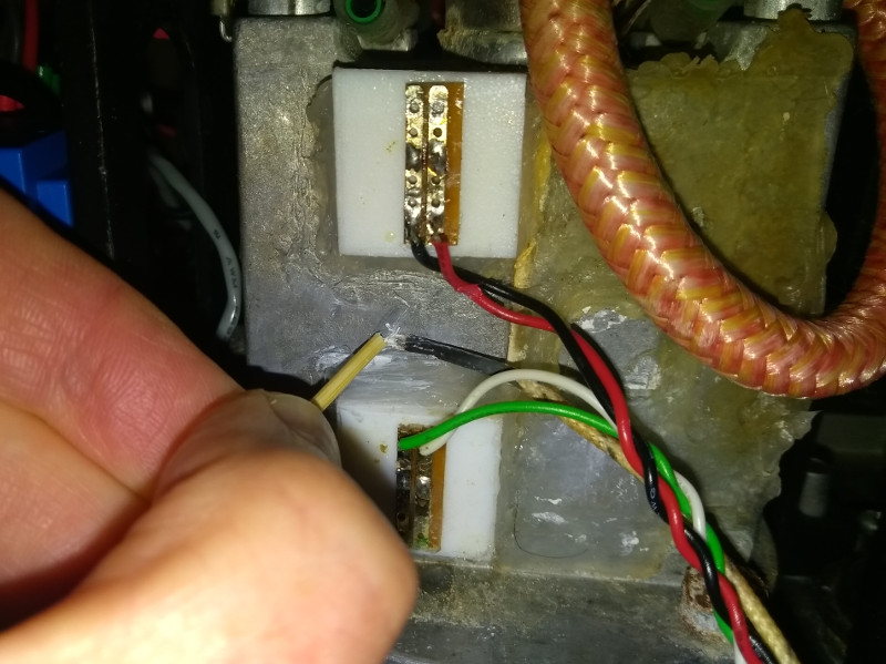
I already have two PT100 probes mounted in blocks of PTFE which are glued on the top and bottom of the front face. These give two of the measuring points and are available in all the tests I conducted.
For the other three points, I have a K Type thermocouple3From my multimeter.. This is how I wired it in. I ran three experiments, one for each of the positions for the K Type probe. In each case I heated the boiler to about 100°C (heating for 38s at 2.5kW).
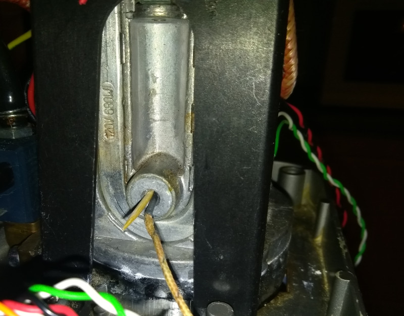
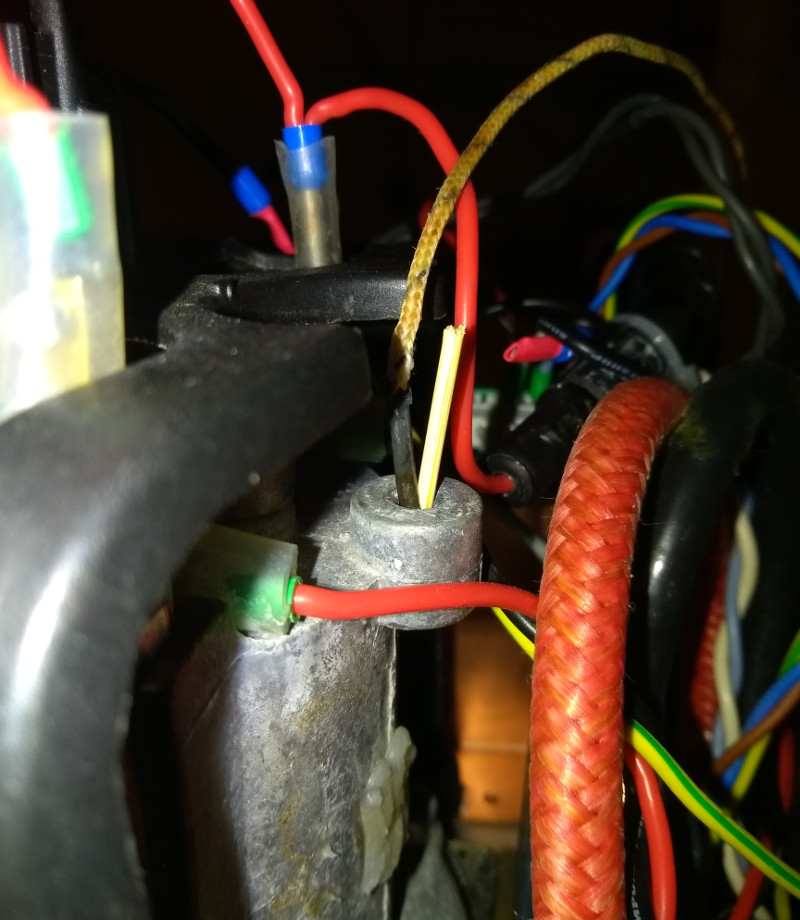
In all three cases, I coated the probe with heatsink compound to improve thermal conductivity. For the M4 threads, I jammed the probe into the side of the hole with a toothpick4Classy yes?.
 and
and
 For consistency, I pressed the probe against the middle of the front face using the end of a toothpick for the other reading5This was fiddly. I don’t spare any effort for you my reader. Also I only had the Kapton tape idea after I took the photo.:
 Results
All the data presented below is in this spreadsheet. On each graph, the power curve uses the secondary Y axis which is in Watts. The other curves use the primary Y axis and are in degrees C. The X axis is time in seconds.
The middle of the front face should give us an idea of how well the K Type probe + toothpick idea works as it is most directly comparable to the two PT100 probe points. Here it is:
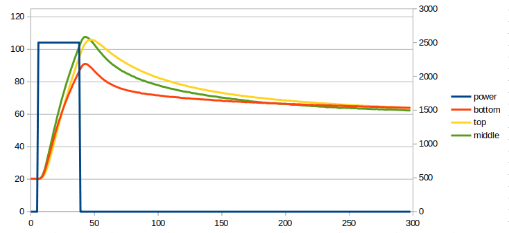
The K Type probe is the green trace. It responds faster than the two PT100 probes. I am guessing that is because of the thermal inertia of the PTFE blocks around those probes. We also see a slightly lower asymptotic temperature for the green trace but should not read anything into this. It is likely due to an inaccuracy relating to the way I read the absolute temperature of the end of the probe leads.
On the whole all three probes are very responsive, with a clear increase from starting temperature within 3s of power being applied. The response when power was removed is the same for the bottom and middle probes and a little slower for the top probe. However this is a change from one very much non-steady state to another non-steady state. I think the initial response is the most important.
The top probe records a higher temperature than the bottom probe. This is presumably due to convection currents inside the boiler and is good news – it means the probe is quite sensitive to actual water temperature.
We can now compare this with the results for the brew thermostat mounting point:
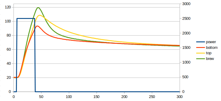 The top and bottom curves are close to the previous results but not exactly the same. In a perfect test system, they would be identical but there are two main parameters over which I had little control: ambient temperature and mains AC voltage. These do vary slightly over time and since I had to wait hours between tests for the boiler to cool, we can expect the slight variations we see.
The clear difference here is the green trace, which is the K Type probe which has moved to the brew thermostat mounting point. This is a lug of aluminium nestling inside the curve of one of the U-shaped boiler elements. Again all three curves have responded within 3s of power being applied but the green trace takes about 3s longer to respond to power being removed. The green trace also gets a lot hotter than in the previous experiment. I hypothesise that these differences are likely because this probe is more influenced by element temperature than water temperature and that the thermal inertia of the mounting point is higher.
I think the middle of the front face slightly beats this mounting point both for responsiveness and for being closer to the temperature of the water. But it is close and the M4 hole is a major point in its favour. Then again, the front face lends itself better to a probe stuck on with Kapton tape.
Finally, there is the steam thermostat mounting point:
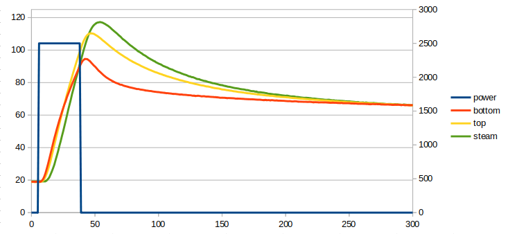 Um, no. Just no. This is the worst position in terms of both water temperature and latency.
Water flow rate in steam mode
In addition, there is another question that is really worth asking: is there any value in having more than one probe? I think there is. A difficult problem when steaming is to know how fast to pump water into the boiler. Too slow and the boiler runs dry. Too fast and the steam ends up mixed with water. But can we tell from looking at the difference between the bottom and top probes whether the water level is getting too low? If so a negative feedback algorithm could be implemented which fills the boiler at a rate which is determined by the temperature difference between top and bottom.
I have tested for this by heating the boiler to around 80°C at 2.5kW and then dropping to 1kW with the steam valve open and running it until the boiler began to run dry. This time I only measured the bottom and top probe points using my PT100 probes. Here are the curves:
 This is fab. My interpretation is: at first the bottom probe is slightly ahead because there is more actual U-shaped boiler heating element at the bottom of the boiler. At around 26s the top probe point moves ahead as water convection inside the boiler takes precedence. Once the power switches to 1kW at 35s, both temperatures become strongly influenced by water temperature with the water at the top already at boiling point and the water at the bottom still below boiling point (and actually slightly colder than the boiler shell which has been partly driven by the 2.5kW heating element until now). Slowly the bottom temperature rises to boiling point, and at about 110s temperature rise drops right off as the latent heat of vaporisation equalises with the 1kW input power. At this point the extra heating element at the bottom of the U takes precedence again and the bottom temperature becomes slightly higher than the top temperature. But at 224s, enough water has evaporated that the top of the boiler is no longer wet and no longer held back by latent heat of vaporisation. The temperatures just diverge from here until, between 300s and 350s, the boiler empties completely and the bottom begins to heat rapidly again.
But in all of this it is the bend in the yellow curve at 224s that I was really looking for. This is great news for a water flow rate control algorithm. Watch this space…
Update: this may not be as easy as I hoped because of two things. First, who wants to wait for the top and bottom temperatures to equalise after the 2.5kW initial heating. Going by the graph above, that’s something like 80s. Second, I suspect injecting water cools the bottom of the boiler a lot more than the top. Both of these factors can lead to a top probe which is a lot hotter than the bottom probe even when the boiler is completely full.
| ↑1 | Especially considering how kindly they made those M4 holes available. |
|---|---|
| ↑2 | i.e. we are sort of doing science here but also, I do not have enough time to be completely thorough. |
| ↑3 | From my multimeter. |
| ↑4 | Classy yes? |
| ↑5 | This was fiddly. I don’t spare any effort for you my reader. Also I only had the Kapton tape idea after I took the photo. |