I have not found it easy to design a cheap and reliable temperature probe which can easily be mounted on the Gaggia boiler. If you have a simple solution, I would love to hear about it.
Here I document my present probe design and an idea I have just had which is really simple and obvious to me since I built a 3D printer but wasn’t before.
There are also some notes at the end about types of devices which could be used for temperature probes and how to use them with the rev2 board.
Mounting the probe
I know some people have mounted probes inside an M4 screw thread, but that sounds quite tricky and requires particular tools and material so I have never tried it. My first probe was a PT1000 device mounted on a piece of stripboard which I held pressed against the boiler with cable ties. This was very unreliable as it was prone to slipping and the cable ties did not last even though I made silicone spacers to keep them from contacting the metal of the boiler.
Present design
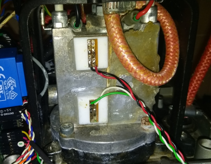
My present probes (I installed two, one at the bottom of the boiler and one at the top so that I can see difference in water temperature caused by convection) are PT100 devices mounted on 20mmx20mmx7mm blocks of PTFE. I drilled a small cavity (about 4mm diameter and 2mm deep) in the center of the PTFE block to hold the PT100 device and a hole (about 2mm diameter) through the bock for the wires. Then I glued it in with silicone sealant.
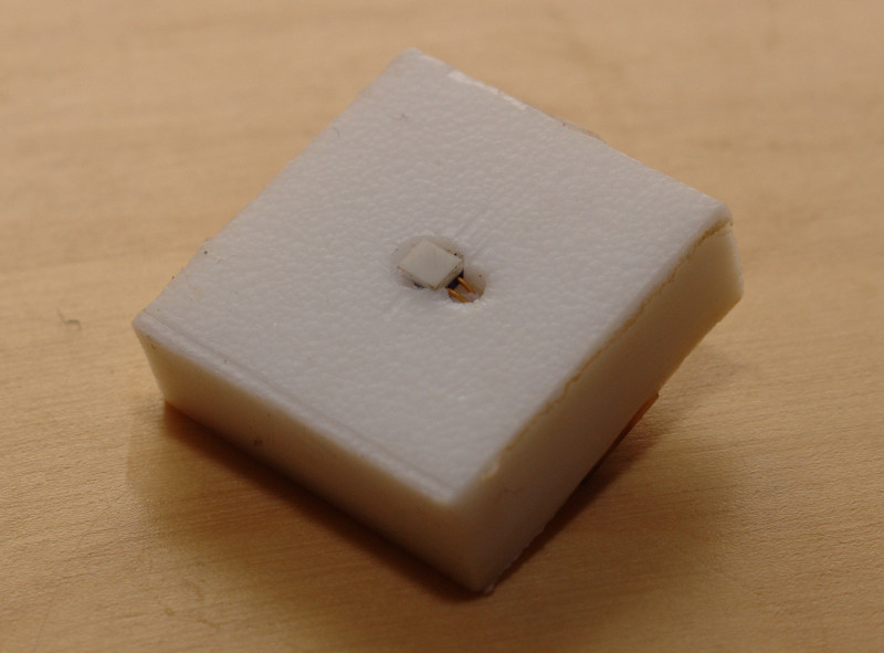 I keep the leads separated by putting one of them in a PTFE sleeve. On the other side of the PTFE block, they are soldered into a small piece of stripboard which is superglued to the PTFE block and which acts as a terminal point for wires to the controller.
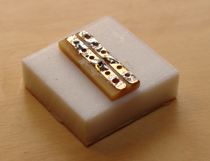 The entire assembly is glued to the side of the boiler with a thin layer of silicone glue and with a bevel of silicone glue around the edges.
 Caveats
There are several downsides to this design:
- It only works on flat surfaces.
- Silicone glue (if it isn’t the expensive high temperature stuff) has additives that cannot handle the temperature and they evaporate making an unpleasant acrid smoke for the first few uses of the machine.
- Silicone and PTFE (Teflon) are legendary for having non-stick surfaces. The superglue has done fairly well holding the stripboard onto the PTFE because there isn’t a great deal of mechanical stress but I have had to reglue one of them and I can see this will have to happen again from time to time. Also I imagine the whole block will eventually come off the boiler and need to be glued back on along with all the associated unpleasant acrid smoke.
- The PTFE blocks have thermal inertia which slows the response of the probes to temperature changes. (Although the response is still good enough and my control algorithm handles the latency. But it’s the principle of the thing.)
A much better idea?
Since getting into 3D printing, a whole new world of high temperature design has opened up to me. In particular, I now know that you can buy an NTC thermistor already mounted on a lead for really quite cheap (I just had a look on ebay and immediately found one for £1.40 including P&P). And I know about Kapton1that’s a brand name – the stuff is polyimide tape which is a fantastic high temperature plastic sticky tape.
I now think there is a really easy solution – stick a 3D printer thermistor to the surface of the boiler with Kapton tape. This will work on curved surfaces, has a really low thermal inertia, involves very little work and is pretty cheap. (Bearing in mind how many uses the roll of Kapton tape will have in your future life!)
Types of devices
So much for how we mount a PT100 device. The rev 2 schematic assumes that probes will be PT100 devices. For other devices, different resistor networks are needed to feed the op amps. Actually, even for PT100 the rev2 schematic could do with a change and some explanation is also needed about jumpers. So…
PT100
PT100 devices must be in series with each other and with IC4. So for one PT100 device, SJ7 will be bridged (with solder) and the probe will be connected to PROBE1. For two, SJ6 will also be bridged and the second device will be on PROBE2. For three, the same applies to SJ5 and PROBE3. The idea was to power all these series devices directly off 5V by bridging one of SJ2, SJ3 or SJ4, depending on the number of PT100 probes. But I am now using a 2k2 resistor instead of a solder bridge. More on this shortly.
The resistance of a PT100 device is roughly linear with temperature. The 1.8V regulator IC4 and 1k8 resistor R42 cause a constant current to flow through all PT100 probes. It should be 1mA but, annoyingly, the AVR’s AREF port draws about 50uA off the 1.8V reference so it is actually about 1.05mA. Anyway, the upshot is that resistance is directly proportional to the voltage dropped across each PT100 device. And as the resistance is roughly linear with temperature, so is the voltage across the device. This means that the resolution of the measurement is approximately the same across the whole measurement range and works out to just over 0.1°C.
I found, when commissioning the rev2 board, that the 5V supply can be quite rough when powered off USB. Unfortunately, C18-C23 and C25 end up conducting this AC signal to ground. So in addition to the constant 1.05mA, there is a high frequency current through the probes and a corresponding high frequency differential voltage across the probes. Using a 2k2 resistor rather than a solder bridge for SJ2/SJ3/SJ4 causes this signal to be almost completely dropped across this 2k2 resistor. Larger values for the input capacitor closest to the 2k2 resistor would also help (that’s C18, C20 or C22).
K Type Thermocouple
These are quite common. I have one that came with my multimeter. This device also produces a voltage that is roughly linear with temperature for the range of temperatures we care about. However, the voltage range is about 1 tenth of the range we get for a PT100 device conducting 1.05mA. So the 100k 1% input resistors (e.g. R27 and R28) need to be replaced with 10k 1% resistors. This gives an output voltage that is roughly linear with temperature, which is great.
I did previously think that the op amp would need a negative rail below 0V for a thermocouple probe to work because the probe (assuming it is uninsulated as mine is) is in electrical contact with the boiler which is earthed and the rev2 board’s GND is also earthed. So one side of the thermocouple will generally have a negative voltage with respect to GND. However for the working range of temperatures we care about the op amp’s output will always be >= 0V and so at least one of the inputs to the op amp must be connected entirely to non-negative voltages. Since the feedback circuit ensures that both inputs to the op amp are equal, this means both inputs will always be non-negative even when one side of the thermocouple probe is negative. So a negative power supply is not needed and C3, C4, D7 and D8 can be omitted and C13 bridged on the rev 2 board2This is a good thing because the negative supply is a bit noisy and the track routing causes this noise to affect the op amp inputs! Definitely leave the negative supply out!.
With a thermocouple probe you do also need another temperature device because the probe’s voltage is relative, not absolute. It is related to the difference in temperature between the probe and the end of the probe leads. I had hoped to use the AVR’s internal temperature probe to measure the ambient temperature around the controller board and, hence, the temperature at the end of the probe lead. However I have found that the AVR’s temperature sensor is very sensitive to differences in VCC (so on USB power you get quite different readings), it is noisy and it is badly affected by self-heating of the AVR.
An alternative would be to use one of the other PROBE inputs to get the absolute temperature needed for using a thermocouple. An LM35 device would work well for this whereas such a device could not be used to measure the temperature of the boiler directly because its maximum temperature is less than the boiler temperature needed for steam.
You may ask what the point is of using a K Type probe if another device is also needed. Answer: they can be quite cheap and, being all-metal, they are rugged. You could, for example, squash one under a washer with an M4 screw on one of Gaggia’s thermostat mounting points.
NTC Thermistors
These are an increasingly attractive idea as they are used widely for 3D printers. So you can get a device already connected up to a lead with a Dupont header for quite cheap.
Their response curve, however is highly non-linear. Here’s the resistance vs temperature curve for a typical 100k, beta=3950 device:
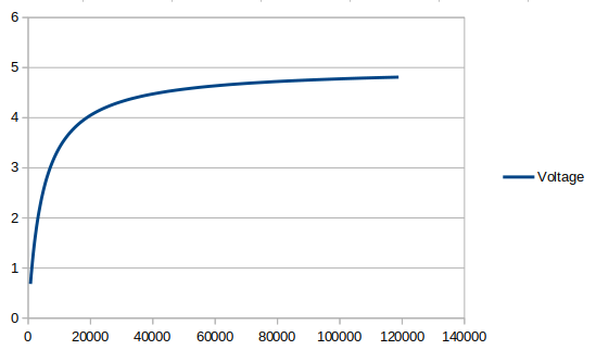
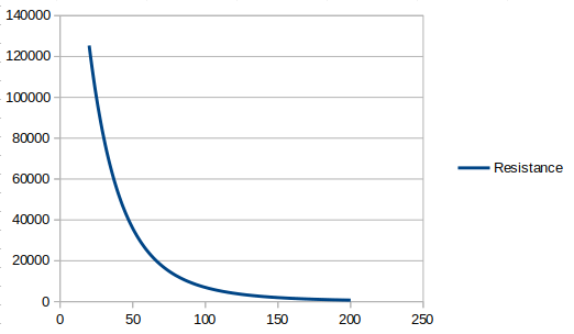 Conveniently, though,you can map resistance to voltage in a compensating nonlinear fashion with a simple series circuit that goes 5V -> 4k7 resistor -> thermistor -> GND3As a bonus, I did no work at all to design this circuit. I simply borrowed the idea complete with the value 4k7 from the RAMPS 3D printer controller board.. The voltage across the thermistor then maps to thermistor resistance like this:
 And the net relationship between temperature and voltage is:
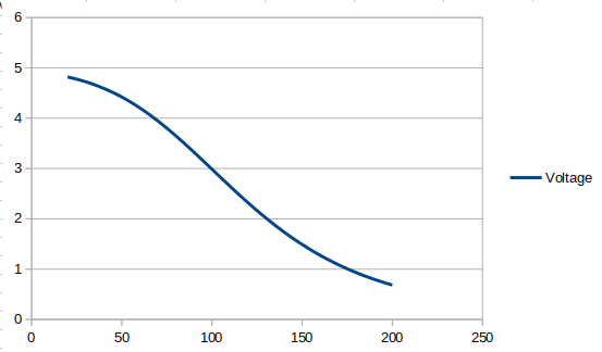 Which is nicely close to linear.
The voltage response here is around 58 times the response for the PT100 device with a 1.05mA current. So if your were using PROBE3, for example, this is what you’d do: replace the 100k resistors R27, R28 with 1M. Replace the 3M3 resistors R23, R25 with 560k. Replace the 1M8 resistors R24, R26 with 270k or 330k. SJ1 has a 4k7 resistor. C19 bridged. All resistors 1% tolerance. [Edit: I wasn’t really thinking this through. R24 and R26 need to be unpopulated or very different values to what I said. Otherwise the measurement range shifts too far away from the range we want. Also, it would be far better if the curve had a positive gradient as with the other two probe types. I’ll get some better values at some point. For now leave R24 and R26 unpopulated.]
| ↑1 | that’s a brand name – the stuff is polyimide |
|---|---|
| ↑2 | This is a good thing because the negative supply is a bit noisy and the track routing causes this noise to affect the op amp inputs! Definitely leave the negative supply out! |
| ↑3 | As a bonus, I did no work at all to design this circuit. I simply borrowed the idea complete with the value 4k7 from the RAMPS 3D printer controller board. |