My original version (let’s call it ‘rev 0′1I never wrote a page for this ancient version in case you’re wondering.) of the controller had an Atmel AVR microcontroller soldered directly onto the board and I had to muck about with serial to USB converters. These days Arduino boards can be bought cheap (for less than a pound on ebay if you’re willing to wait for one to come from China2And if you’re okay with importing from China. I worry about this kind of thing.).
So here are the Eagle CAD files for an Arduino Nano “shield” I designed to do the job: coffeepidshield.zip. (Or if you just want a PDF, it’s coffeepidshield.)
Or if you just want to get a board printed, here are the Gerber files: coffeepidshield.gerber.zip. (Caveat Emptor: I discovered some things I would change about the board if I printed more. See my comments below.) I have some spare boards as the cheapest price I could get for printing was for 10 boards. Let me know if you want one. I have 2 left as of Oct 2019. You might want to wait for rev 2, though – although I am not sure when I’ll complete that.
And here is the Arduino project file for driving the wee beastie: coffeepid.ino. (Here’s an older one I originally posted: coffeepid.ino.)
Parts list
I got most of my parts at CPC or the related Farnell3In the USA Newark is part of the same group., so I include CPC part numbers:
- C1: 1000uF 16V CA05731.
- C4: 1nF 0603 CA06574.
- C5: 470nF 0603 CA06405.
- All other caps: 10nF 0603 CA06573. (Note: you probably won’t populate C10-C15, see below.)
- D3: 1A diode SC11345. (Can’t for the life of me think why I picked this rectifier diode, a 200mA one would do.)
- IC1: LM2904D SC07981.
- OK1-OK3: MOC3022-M optocouple SC12309.
- R1-R3: 470Ω 1206 RE03984.
- R4-R6: 330Ω 240VAC 1/4W carbon film. (e.g. RE03797. Don’t buy them individually, buy an assortment pack).
- R10, R11, R20: 2.7kΩ 240VAC 1/4W carbon film. (Ditto.)
- R7: 1.2kΩ 0805 RE03939.
- R9: 2kΩ 1% 0805 RE03941.
- R12: 270kΩ 1% 0805 RE03968.
- R14: 1.5MΩ 1% 0805 RE07151.
- R15: 47kΩ 1% 0805 RE03959.
- R16: 3.3MΩ 1% 0805 RE07153.
- R18: 330kΩ 0805 RE03970.
- R19: 100kΩ 0805 RE03963.
- SG1: piezo buzzer LS03804. (Make sure it is one that makes a tone when you apply a DC voltage, rather than one that needs a waveform. Also look for one that is loud at 5V.)
- T1, T3: 8A snubberless isolated TRIAC BTA08-600CWRG SC11522.
- T2: 24A isolated TRIAC BTA24-600BWRG SC11517.
- TR1: 1.5VA 2x9V isolation transformer TF01239. (I used the BLOCK transformer but I see MYRRA and VIGORTRONIX seem to offer cheaper equivalents as of April 2020. A 1x9V secondary winding would also be fine as long as the pins match and the power is 1.5VA or more. On the rev 2 board, I’ll make space for two primary windings so 1x230V or 2x115V will work.)
- U1: not populated (see below about making solder bridges).
- 2 x 15 pin female headers for Arduino Nano (something like CN18766 but with more contacts).
- 3 x 2-pin male headers for brew & steam switches and for temperature probe (gold plated in latter case). (Break them off one of these: CN18761.)
- 1 x 3-pin male header for flow meter. (Ditto.)
- 4 x M3 PCB standoffs (e.g. PC01257 or anything to fit a 3mm hole).
- Heater, solenoid and pump 2-pin terminals: CN11533.
- Mains (live, neutral, earth) 3-pin terminal: CN11534.
I make that a little over £15, although some components have to be bought in bulk, which will make it more expensive and give you spares. Why not buy extra and make up some kits for your friends for Christmas?
Sensors
For all of this to be any value, you will at least need some kind of temperature probe. These are, frankly, a bit of a pest. No one makes a nice probe you can just attach to a Gaggia machine. I have designed the circuit and firmware for a PT100 device (like SN36364). The resistor network around IC1 is carefully arranged so that for resistances from about 97Ω to 163Ω, ADC pin A0 will read values in the range 0 to 1023. This corresponds to temperatures from just below 0°C to around 160°C. With suitable resistors and firmware, any kind of NTC, PTC or thermocouple probe could be used.
I leave the construction of a suitable probe to the reader. (Top tip, though, don’t mount your probe in the fat chunks of aluminium where the original bimetallic thermostats are mounted – it takes a long time for temperature changes to propagate through these. Go for half way up one of the side walls where the boiler shell is thinnest.) [Edit: I later wondered whether I might be mistaken about this. Using the rev 2 board, I have done some testing to determine a good mounting point for a probe. I have also made progress on ways to mount a probe.]
You will also, likely, want a flow meter, although some of the goodness can happen even without one. I used a Digmesa device like this, but they’re hard to get hold of in their own right. The trick is to buy (ebay again) one as a spare part for a common coffee machine. Search, for example, for “saeco flow meter”. Many of the devices on ebay have a min flow rate of 300ml/min. That is way too high, so watch out for that. What I really wanted was a Digmesa device with a 1mm nozzle, but I got one with a 1.2mm nozzle, which is okay for double shots, but very much on the edge of okay for single shots. See my comments below under caveats for pinouts of the flow meter header. [Edit: I now have a second hand Baby Twin (“for parts” for £30 on ebay – would you believe?) and I see it has exactly the same flow meter.]
For both temperature probe and flow meter, you’ll get best results if you calibrate them and update the constants in the firmware source code. If you get a different flow meter from mine, you’ll definitely need to calibrate it. I did my calibration by playing with the source code and taking measurements with a multimeter (temp probe) and graduated beaker (flow meter). Have fun with that.
Wiring
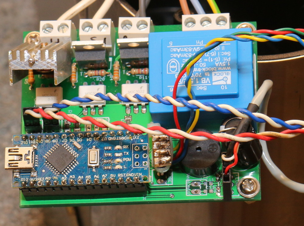
Finally, you need to do some wiring. You’ll need wires with two and three pin header connectors. I ripped some out of old PC cases. You could also buy them on ebay. All the wire pairs should be twisted to reduce electromagnetic noise. (Really: fast switching of high currents into the boiler element, for example, can trigger all sorts of nasty pulses on the digital inputs, with all kinds of odd results like the Arduino rebooting.) Ideally make twisted pairs out of the wires to the temperature probe, the brew and steam switches, the flow meter (a twisted triple) and all the mains wire pairs.
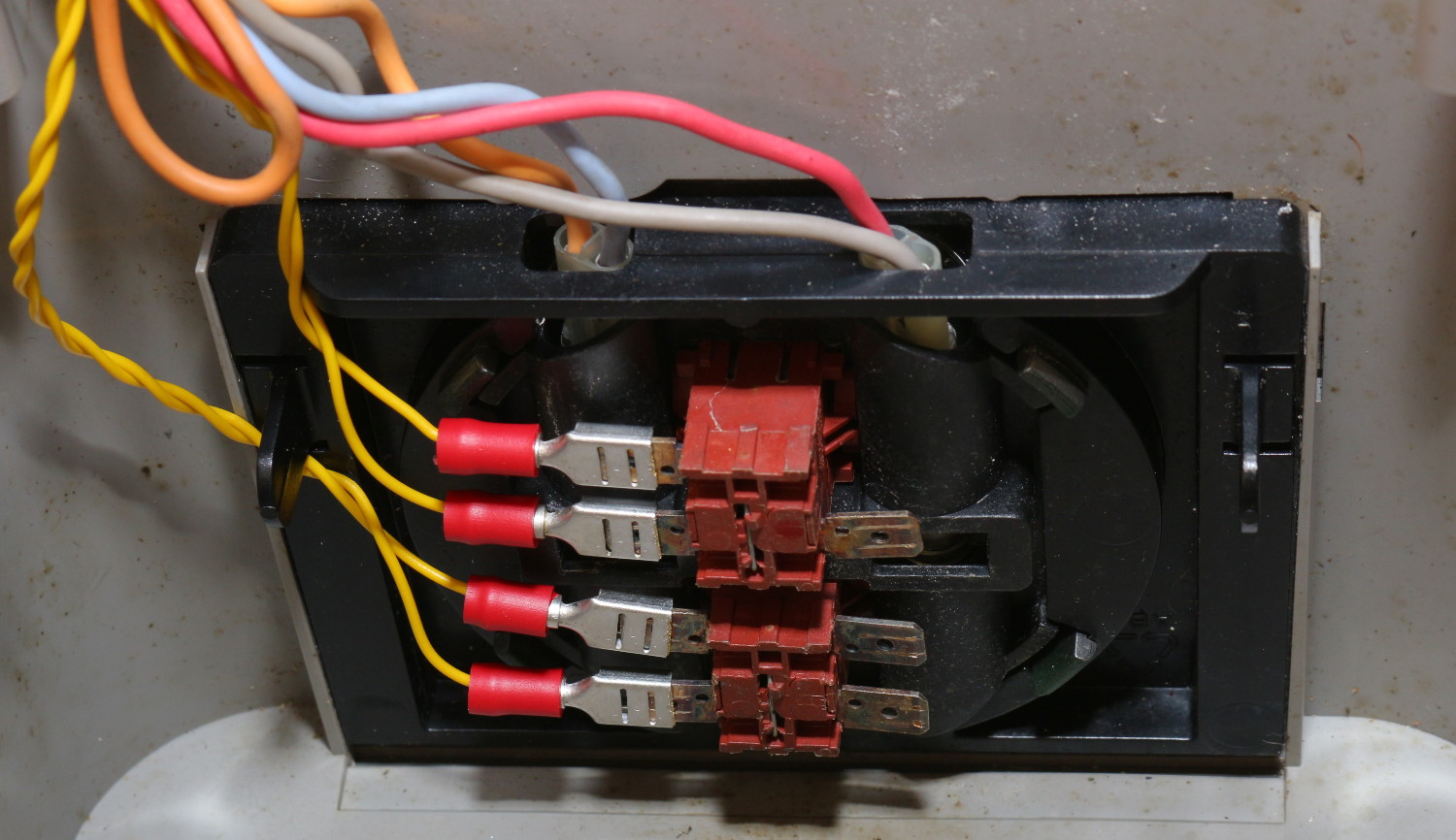
Connect the PUMP_SW and STEAM_SW headers to the pump and steam switches (after carefully disconnecting the mains voltage cables that come connected to these switches from the factory).
The temperature probe should be connected to PROBE1 (PROBE2 is for later expansion).
The mains supply 3-pin terminal is marked LNE for live, neutral and earth, which is the order of the pins with earth closest to the corner of the board.
The HEATER (i.e. boiler element), SOLENOID and PUMP terminals have one pin connected to mains neutral the other to a TRIAC which switches mains live to the device. So, ideally, connect the two ends of the device to the two pins of the terminal. Having said that, a really good idea is to keep the steam mode thermostat in series with the boiler. That way, the boiler cannot be overheated. I have saved myself from bad firmware and other design errors countless times with this trick. And, very very definitely keep the thermal fuse inline with the boiler wiring: this is your last bastion of defence against stupidity. (Thankfully I’ve never needed it owing to the aforementioned steam thermostat.)
Important note: in the version of the software above, I have swapped the SOLENOID and HEATER pinouts so the heater is now the centre terminal. (See caveats below for an explanation.)
In principle, you could rip out all of the old wiring. I left mine in, but disconnected most of the connectors because a) I didn’t have a crimp connector for the boiler’s terminal pins, b) it was the easiest way to keep the thermal fuse in line and c) I wanted two of the neon lights still in the circuit so I could see whether the machine was switched on and whether the boiler is being heated. Your wiring may differ to mine, but for my Gaggia Baby Class, this entailed leaving the orange and blue wires connected to live and neutral, leaving the blue wires connected to the boiler and the solenoid and leaving the red wire connected to the boiler and steam thermostat. This also meant only connecting one wire from the HEATER and SOLENOID terminals to the positive side of the boiler (i.e. the steam thermostat) and the solenoid because they were already connected to neutral via the blue wires.
Caveats
You’ll always regret your design and want to do something different just as soon as the physical product is set in stone. One set of things I wish to change is connector labelling. You can’t see the labels HEATER, SOLENOID, PUMP and MAINS_LNE once the terminals are soldered onto the board. Doh! You might want to write these onto the terminals with a permanent marker during assembly.
And then there’s the flow meter, which requires 5V, GND and count pins. I haven’t labelled these. So, for reference, 5V is closest to the edge of the board, GND is the middle pin and count is furthest from the edge of the board.
The other daft, daft design flaw was not leaving space for a heatsink on T2. This TRIAC switches the boiler element, which conducts about 5A4I wrote this before I begin tinkering with doubling the boiler power! when on full-time (i.e. during preheat and when steaming milk). Suitable TRIACs will drop around a volt at this current, generating in the order of 5W. Hmm, how hot will a bare TO-220 get at 5W? Well, as expected, the datasheets tell you this, but I didn’t look. The answer is 60°C/W, or 300°C above ambient. Rookie error number 1. Rookie error number 2 follows close behind: TRIACs must never, never get hotter than 125°C, otherwise they just switch on permanently until they cool down again or heat to self-destruct temperature.
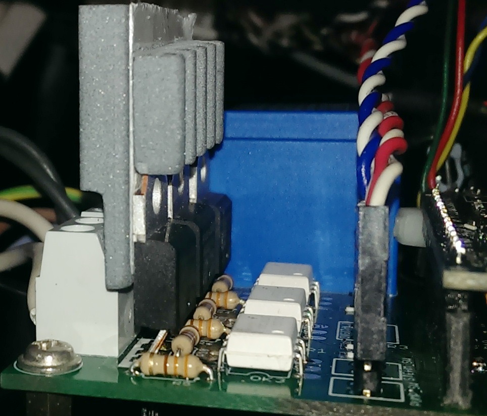
So, T2 needs a heatsink. This can be contrived, despite space not being left for one (not the mess in the picture above – although that does work). By bending a zig-zag into the TRIAC pins, you can get about 2.5mm between the terminals and the TRIACs. This leaves space for a 40mmx40mm heatsink to be placed vertically behind all three TRIACs. Get one with fins and a sticky pad, file off the bottom 7mm of the fins so the thickness is less than 2.5mm. To reduce the overall height and increase the efficiency, you can also cut the top 13mm off the heatsink and stick it onto the top of the remaining piece back to back. Or even on to the front of the metal heatsink tabs on the TRIACs. I didn’t make a particularly pretty job of this, but it works okay (using a nifty ceramic heat sink which is easy to work – although also more fragile than aluminium):
It is also a good idea to spec T2 for as high a current as you can because higher spec TRIACs tend to produce less power for a given current. This is why I spec a 24A TRIAC for T2. An improved board layout would have more space between the TRIACs and the terminals. I have already made one improvement by moving the HEATER terminal to the middle in software, so the SOLENOID and HEATER labels on the board are now wrong. [Edit: I now wonder whether a batter trick would be to bolt a 50mmx60mm copper sheet onto the TRIACs and bend it over and mount the heatsink on that. Worst case scenario, use a 40mmx40mm water-cooled CPU heatsink with the inlet water running through it. This is my plan for if all goes wrong on the rev 2 board.]
Finally, be aware that TRIACs come in insulated and uninsulated versions. The latter have the metal tab connected to pin 2, which is at mains live voltage. So you’d have exposed metal bits connected to 240VAC. And with a metal heatsink, quite large exposed metal bits. The insulated ones are slightly less efficient at cooling but they don’t kill people. The TRIACs I spec above are all insulated.
Unpopulated parts
I have visions of using two temperature probes one day, one at the top of the boiler and one at the bottom. This way I can better determine whether the boiler is full and/or whether temperatures have stabilised. The board is designed to use a SN74CBTLV3257PW multiplexer to switch between probes. For now, the firmware knows nothing of this and I have not populated this device on my board. Instead, I have made a solder bridge between pins 6 and 7 and another one between pins 9 and 10. I have also not populated the PROBE2 header or its associated noise reduction 10nF capacitor C10. [Update: I have now populated these parts and they work fine.]
In planning, I also wondered whether I might, one day, think up other clever things to do which might need some of the presently unused Arduino pins. So I expose some of these via the DIGITALIO and ANALOGIO headers. These, too, I have not populated and neither have I populated C11-C15, their 10nF caps. [Edit: but I stupidly did not make any 5V or GND pins available, which I realised when I wanted to add a water level meter circuit. Rev 2 will remedy this oversight.]
Return to main coffee machine page.
Hi Tom,
Wonderful stuff you’ve built here. Well done!
Just wondering if you got around to comparing the temperature responses on the various spots around the boiler (mentioned above you were planning to do this with the rev 2 board)? If so, where did you find to be the best place to mount the temperature probe?
I wonder if you considered digital sensor such as TSIC306?
Cheers.
Vince
I haven’t done anything systematic yet. I have used a probe at the top of the sidewall and one at the bottom. IIRC the one at the top was a bit hotter but their responses were not markedly different. At some point I want to see whether it is possible to determine if the water level has dropped during steam mode by comparing the temperatures. I also want to see how quick the response is at the mounting point for the Gaggia probe. My theory is that it is slower because of the thermal inertia of the cylinder of aluminium that comprises mounting point. I have not done this yet.
If the response is good, a whole new possibility opens up with PT100 cartridges which are now available for high temperature hotends on 3D printers. e.g. this one.
It’s 3D printers, actually, that have slowed down the work on the rev 2 board. During lockdown, I finally got round to building the one I started 7 years ago. And I am also building a recyclebot to make filament for the 3D printer from plastic milk bottles. Eventually, the 3D printer will print a milk-bottle-derived backplane for the rev 2 board to shield the mains voltage contacts on the bottom of the PCB.
I must blog about the printer and recyclebot at some point.
I have now made progress with this. See here.
I also realise now that I never responded to the question about the TSIC306. I have in the past looked at the similar LM35. One problem with both devices is that their maximum operating temperature is 150°C whereas you need a higher temperature than that for a good head of steam. Another is figuring out a good way to mount one.