My new controller board is complete and has been delivering good coffee for several months now.
Here are some of the improvements:
- Much better provision for heatsinking the TRIACs. With an option to use water cooling (as it turns out I haven’t needed it, but it would definitely mean no more TRIAC overheating ever if I implemented it).
- Potential to use thermocouple or NTC temperature probes.
- Up to 3 temperature probes. This would allow for an algorithm to correctly control water flow rate when steaming and still give a spare probe (maybe to check the TRIACs don’t overheat or for a Gaggia Baby Twin steam boiler).
- Water level probe.
- Support for Gaggia Baby Twin steam boiler. (Extra temperature input and drive TRIAC).
- Louder piezo buzzer.
- 5V and GND exposed via pins for add-ons.
- TWI interface available. (Rather than using the pins for something else as I did previously!). This allows communication with add-ons and (yay!) also with the Baby Twin front panel.
- Power doubling is now done on-board so no external diodes needed. (This is why there are now five TRIACs, one for the steam boiler, one for each element of the main boiler and one for each of the pump and solenoid.)
- Better solution for mounting the board in the coffee machine (assuming you have a Gaggia Baby – any volunteers to do a Gaggia Classic PCB layout?).
- The transformer’s pinouts are arranged so that 120VAC transformers can be used for my coffee modding friends in the USA. (Whilst also still being able to use a 240VAC transformer as well of course.)
The rev2 schematic is coffeepidshield.pdf. Gerber files are here. Eagle files are here. Have a look particularly at DesignNotes.txt in the Eagle files zip for a mine of information. Or get the most up to date info at GitHub.
If you are in the USA or on another 120VAC mains supply, you might find it this bill of materials helpful.
Here’s a picture of the PCB:
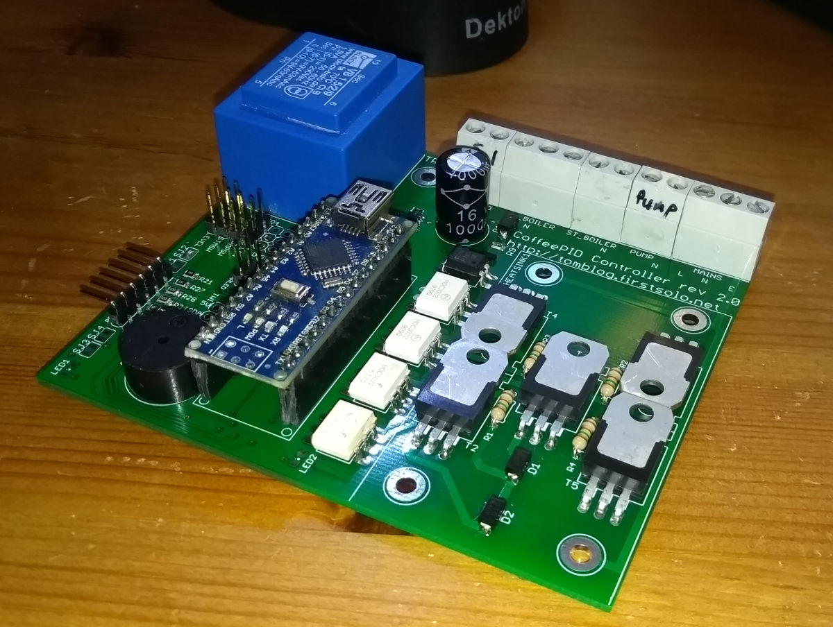
The board is sized to fit where the Gaggia Baby Twin’s PCB mounting bracket lives along the left hand side of the top boiler housing. Here’s a picture of it in place:
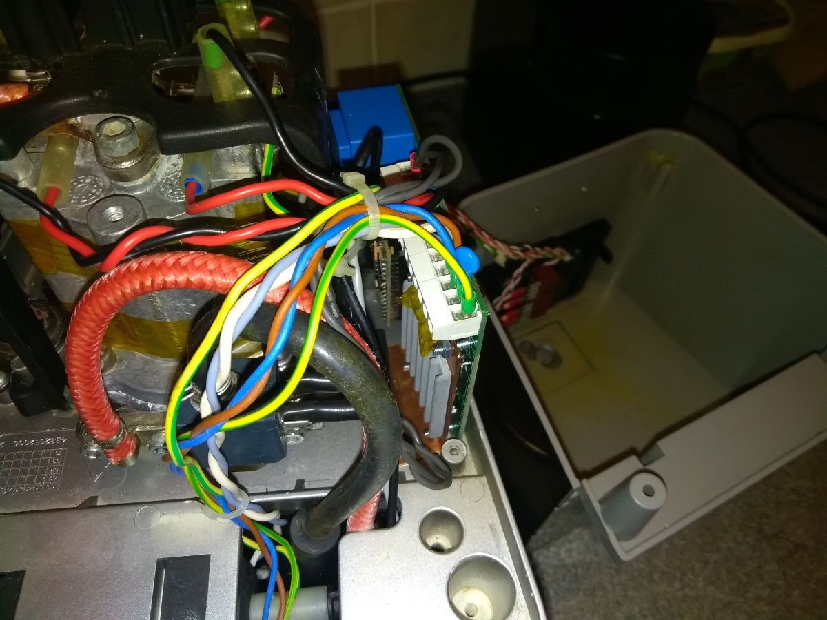
That’s a bit busy so here’s an old bit of PCB giving an idea of the location:
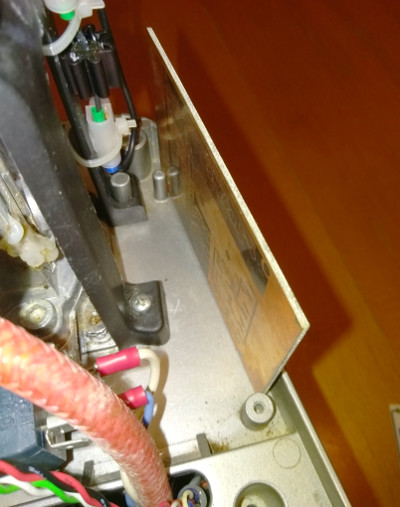
The mounting posts for the Twin PCB bracket help to locate it and I have also bolted the PCB to that nice bit of clear base plate with the heatsink. (Note: those mounting posts break off really easily and are best not to be trusted!) I still need to implement some kind of plastic backing plate to this board to insulate the exposed mains voltage solder pads.
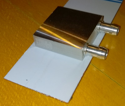
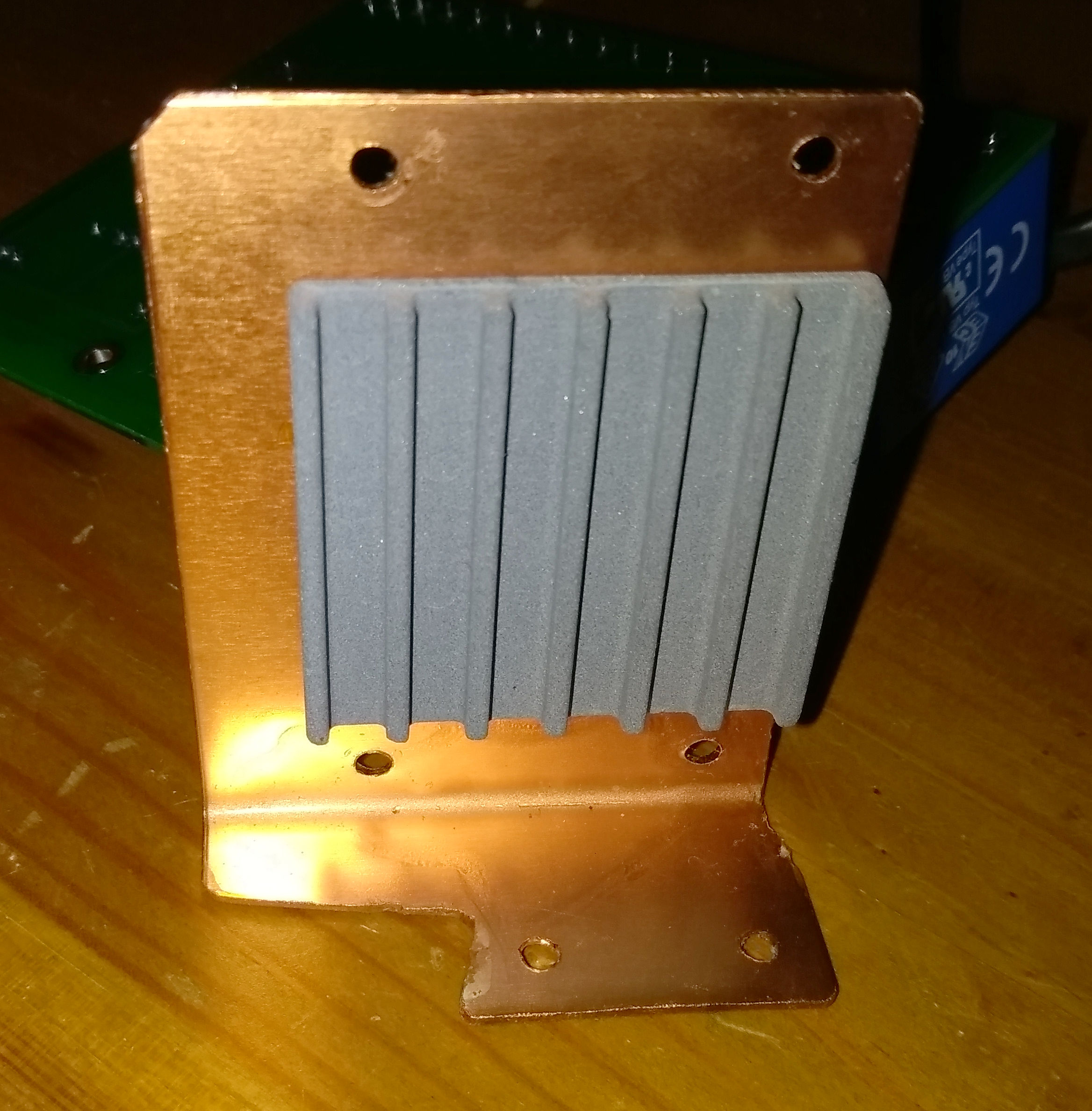
The heatsink is a copper plate I bolted over the TRIACs and bent 90° so it stands flat and doubles as a mounting bracket for the whole board. There is space on the face of the heatsink for a 40mm x 40mm water-cooled CPU heatsink. This could be cooled by water as it flows from the reservoir to the pump. I have found that the ceramic heatsink pictured above seems to be enough though.
Here’s a picture of the water-cooled heatsink and the pristine copper sheet (still in plastic film):
And here’s the finished product before mounting (I loved the colour of the copper so I sprayed it with lacquer to keep it from oxidising):
In commissioning, I found the following errors (despite very carefully checking everything over, there are somehow always errors when the board has actually been printed!).
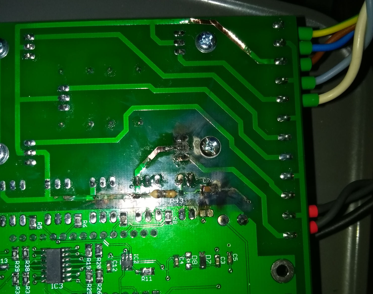
- R43 is specced as being able to drop 400V but is an 0803 component – no such resistor exists! I have a workaround mod to the board to handle this.
- R43 and C26 form an RLC circuit with the inductance in the mains wiring and PCB tracks. If the inductance is high enough (and it can be in a normal scenario), this circuit can have oscillations with a peak voltage way above than the 340V mains peak1Caused by the inrush current if you switch on in the middle of a mains cycle.. This caused a catastrophic failure for me2A lot of arcing and multiple vaporised tracks. This was a sub-optimal outcome.. Replacing R43 with a 100R resistor overdamps the RLC circuit and prevents these peaks. Also, putting a metal oxide varistor across Live and Neutral absorbs spikes and prevents arcing.
- IC2 is connected to PMPSW instead of STMSW. IC2 changes the temperature range measured by the temperature probe so you can have one range for steam mode and another range for brewing mode. I meant it to be connected to STMSW! I have also decided that it was dumb to do this anyway and I am now driving PMPSW from firmware to control IC2 and have connected the pump switch to one of the DIGITALIO pins instead (the Arduino’s D10 pin).
This picture shows the R43 workaround and also the consequences of the over-voltage event.
Anyway, look out for a rev2.1 design at some point.
Hi Tom, not sure if this site is still updated as I can’t see any dates… I have an old Gaggia Baby Dosata with what I think is a dead controller after replacing the therma fuse. I’m not facing forking out for a new controller at around £90 and wondered if this PID controller would replace the factory one. On my machine there are a few buttons on the front for measured single / double shots, to pump water etc and I wondered how these would integrate. Any info greatly appreciated… I miss my Baby.
Yes, I’m still actively updating the site. Just not all that frequently. I have built a 3D printer and that’s taking a lot of my attention at present. Must write about it at some point.
Looking at the parts diagram for the Dosata, I see the internals are all common with the other Gaggia Baby machines and either of my rev1 or rev2 boards would drive it. (And also give you the freedom to improve the algorithms!) A key question is what the communications protocol is between the front panel and the controller board. My guess is it’s just a bunch of wires to the switches/lights. But it could be (as with the Twin) a logical protocol – see my notes on the Twin’s protocol. If it is a logical protocol, you’ll need my rev2 board to be able to interface with the front panel.
I have actually completed the design of the rev2 board and had a bunch printed but I haven’t populated one yet and started testing it. I’m pretty confident about everything except the zero-crossover logic. I modified the latter after the FET burnt and haven’t yet ordered a new FET to test the new design (which is in the boards I printed). Pretty sure it will be okay, though. (Again, my attention has been diverted by the 3D printer!)
Would you like a rev2 board to populate and try out? I’ll e-mail you to get your address.
Hello Tom,
Nice work you have there. Currently, I’m building a Pressure profiling and flow profiling for my gaggia baby, For my circuit, I’m using MOC3041 optocoupler and BT136 triac that switch the Ulka 240V pump. I’m sending the 5V PWM signal to the moc3041 from arduino. I saw your circuit that you used MOC3020 that is non-zero crossing optocoupler. I’m thorn between MOC3021 and MOC3041 for driving the bt136. I know that MOC3021 is a phase angle control optocoupler and MOC3041 just on and off the pump(still full pressure but burst).
Thanks,
Joseph
I suggest the MOC3021 for the simple reason that you probably need to be tracking zero-crossing yourself anyway. So you do not need the MOC3041 to pick the turn-on time for you. And it gives you more flexibility about what method of control to use. (Although see my caveat at the end.)
To recap what you probably already know, I am aware of two main control methods people use:
1. I believe some people use a high frequency PWM signal that chops the mains AC into small pulses. I suspect Gaggia do it this way with the Baby Twin (just from inspecting the controller board.) That would need something like a MOSFET or IGBT instead of TRIAC and opto-coupler. I have never looked into it because I think the electromagnetic noise generated must be rather bad. Also, I don’t like the idea that the only thing separating my logic level board (and its Arduino USB port) from mains is a MOSFET/IGBT gate insulator.
2. Others (like me) use phase angle control to decrease the total energy transmitted in each mains pulse. Still noisy but only at 50Hz and the noise only happens at switch-on so the inherit inductances in all the wiring reduce the rate of change of current. (Switch off of a TRIAC happens at zero-crossing anyway.) For this, you need a non-zero-crossing optocoupler as you observe.
In addition, another option that I’d quite like to experiment with is what I do actually do with the boiler elements. That is to send entire 10ms mains pulses but not to send all of them. It works wonderfully with the boiler, is nicely linear and pretty much infinitely variable. I keep wondering whether it would work with the pump. If I did it this way, an MOC3041 would be suitable. Having said that, an MOC3021 would work just as well as long as I only pulse it at zero-crossover.
Which brings me back top my main point. You need to the mains frequency. It is close to 50Hz but not exactly 50Hz and it’s always changing as the power grid manages load. So you have to measure it real time. If you’re measuring the frequency, you might as well track the zero-crossover as well. And then it doesn’t really matter which optocoupler you pick.
Unless you are planning on really low frequency PWM (much lower than 50Hz). That’s a really simple solution and the MOC3041 would save you tracking zero-crossover. I’d be interested to know whether that works.
Do you have any of these or, perhaps, some other control method in mind?
PS the pump has an internal diode and only ever conducts on alternating mains cycles. Something to watch out for if you end up giving it power on the “wrong” cycles.
Thanks for the quick reply tom.,
Actually, what I’m doing now is sending PWM pulse with lower frequency, around 30Hz to 40Hz. I also tried pulsing it with 5Hz. I’m using arduino timer interrupts timer 1 to send pwm pulse on moc3041. One problem I encounter is the Triac, doesn’t off. Pump still run on negative cycle but on much lower power. I have a 330ohms resistor between gate and MT1 of the BT136 Triac. If I put a snubber circuit of 0.01uf capacitor and a resistor the pump doesn’t turn on.
Also, What do you mean “send entire 10ms mains pulses but not to send all of them” Can you discuss further more about this. I think this is what I’m doing now. I used Timer 1 of arduino uno to send pwm pulses.
With around 35Hz I would expect the circuit mostly not to work because the frequency is too close to 50Hz. The PWM output will be going in and out of phase with mains 50Hz. A lot of the time the waves will be sufficiently in phase for the PWM high pulse to miss the zero-crossover, especially if the PWM duty cycle is low. 5Hz should be much better as every PWM cycle then covers about 10 mains cycles and you should see between 0 and 10 mains cycles powering the pump each PWM cycle.
That’s what I would guess anyway.
What PWM duty cycle values have you tested?
It may well be that the BT136 needs a snubber circuit because the pump is very much an inductive load. I use snubberless TRIACs which work very nicely without a snubber.
What is your 330ohm resistor for?
What do you mean by “negative cycle”? Is that PWM cycle or mains cycle?
My 10ms comment was cryptic, sorry. I meant that each mains half-cycle lasts 10ms. Phase angle control switches on a certain fraction of every one of these 10ms half-cycles. An alternative is simply to turn on some of the half-cycles for the entire 10ms length of the half-cycle. This is what you are doing, but I suspect you’re being a bit hit and miss about which 10ms half-cycles are getting turned on.
Also, do you have an oscilloscope? It helps a huge amount to be able to see what is happening. But major warning: the scope’s ground line will be connected to mains Earth. This makes it tricky to use a scope to view mains waveforms. Not to mention that it can be dangerous to attach probes to mains voltage.
Tom,
330ohm is connected between gate and MT1. It is as per datasheet of moc3041. I think this is to prevent the gate to be in floating state. But im not sure also. For the “negative cycle” i said earlier, sorry for the confusion. What im talking about here is that the Bt136 triac doesn’t turn off once the gate is powered on. I tried to put RC Snubber between mt1 and mt2 pin but the pump doesn’t run with snubber.
Also. Do you have circuit for zero crossing detection? I have here HCPL 817 and PC817 optocouplers. I just don’t know which one is better and the values i need for the resistors.
What I have here is only handheld 1 channel osscilloscope(DSO138)
Getting crowded in the comment section here. Will reply by e-mail.
Hey Tom,
I’ve got a classic and was gonna pull the trigger on another diy PID setup when your project really caught my eye. In Rev1’s edits you mention testing different probing points on the boiler, have you populated a board to try out yet? I’d love to give either rev2 or 1 a shot come January.
Edit: I just saw a pertinent comment I’d missed that answered half of my question. I hope the 3D printer’s going well!
Thanks. I am paused in the middle of making a RecycleBot which should make filament from plastic bottles to feed the 3D printer. I broke the NTC thermistor I was using and the cheapest replacement has the most expensive shipping (from China). Ideally I’ll get to wanting to buy several things at once and that will sort the shipping price out.
I think you probably spotted my reply to another comment saying I haven’t done the comparison between different points yet. Since this is clearly of interest to multiple people maybe I should get a move on.
I do have two spare rev1 boards left but unless you specifically want a smaller footprint, the rev2 board is really the future and I have spares of those as well. I’ll e-mail you about that.
I have now made a lot of progress with this. See here.
Thank you so much for documenting all this and putting it on Github! I’m on a similar journey with my Gaggia Baby Class, and your project is an amazing starting place. I’ll probably need to make some changes for 120V land (Probably need to check the triac current mostly, and might switch to external SSRs for heat, don’t trust those waterblocks not to leech). I’ll also probably add some control/sensors for automating a roaster as well.
You’re welcome Chris. In the end I did not use water cooling. A ceramic heatsink plus bolting the copper heatsink to the housing provided enough cooling. So no external SSRs needed. That’s most of the point of the board really. It implements the SSR circuitry.
As the baby class does not have the second boiler, you have a spare TRIAC that could be used to control a roaster. I am intrigued by that, by the way. Do you plan to integrate it into the coffee machine?
The TRIACs can handle the current at 120V. In fact you’ll have the same average current as I have at 240V. But you won’t get double the boiler power sadly. However since you do not need the TRIACs to block the 340V peak we have you might find a better alternative. Definitely look for insulated TRIACs. Otherwise the copper heatsink will be live!
I have a few coffee modding friends in America and one of them has built my board and sent me his bill of materials. I have been meaning to upload it to my blog. You have prompted me to do that. Details here.
Hi Tom,
Any advice/guidelines for running the low voltage wires? I fried two esp32 boards until I realized my sensor wires were too close to the solenoid valve. Any special protection you have built into your board against surges?
Ouch, frying the boards sounds expensive. I must say I am surprised they fried. I don’t think an AVR-based board would because all inputs have clamping diodes.
Things a well-designed board would have (IMHO):
Thanks, I did number of beginner mistakes, but boards are not that expensive and I’m moving to esp32-s2 which is $5 so … “learning the hard way” tax was not too high.
“Clamping diode” does the job when googling! thanks!
You’re welcome. Learning is always worthwhile.
Other things I thought about after I posted were:
Thanks a lot! This is lots of solid advice I can incorporate for the next revision of my board. The intel manual is great, I’ll need to do some learning anyhow.
Hi, Tom!
Thank you very much for your project. I’m really looking forward to implementing all these features on my Gaggia Baby Twin. Could you please tell me if there are any updates to the PCB and software (there are no commits in GitHub since 2021)
Hi Igor, I have been busy with other projects for the last few years. My Gaggia Baby is still an important part of my daily life and, whilst there are additional features I would love to have time for one day, basically it gives me everything I want. (I’d love to implement a GUI for example.) Do note the comments at the bottom of the page above about things I would change in the design. I think, also, I would actually move the whole zero-crossover circuit to the low voltage side of the transformer. That would probably eliminate the need for D10 and possibly R43 and C26 (I can not remember in exact detail what this RC filter was for but I think it was about meeting dV/dt limits for the JFET).
Anyway do also check out the Gaggiuino project if you haven’t already. It has a very active development community. It is mainly aimed at Gaggia Classic but there are Gaggia Baby owners there. Another potential downside to Gaggiuino (depending on your point of view) is that the project has stopped being open source in an effort to protect it from commercial organisations taking advantage.
Regarding the Baby Twin specifically, I concluded that the extra boiler does not add the value I want because it is only about 1kW. (I have an unmodded twin but it’s just my spare coffee machine for when the Baby Class is down for maintenance.) So you might want to bypass the second boiler. On the other hand, the flow meter is exactly the one I use in my modded machine so that’s a win.